Intelligent Aluminium Extrusion
Architectural Aluminium Extrusion
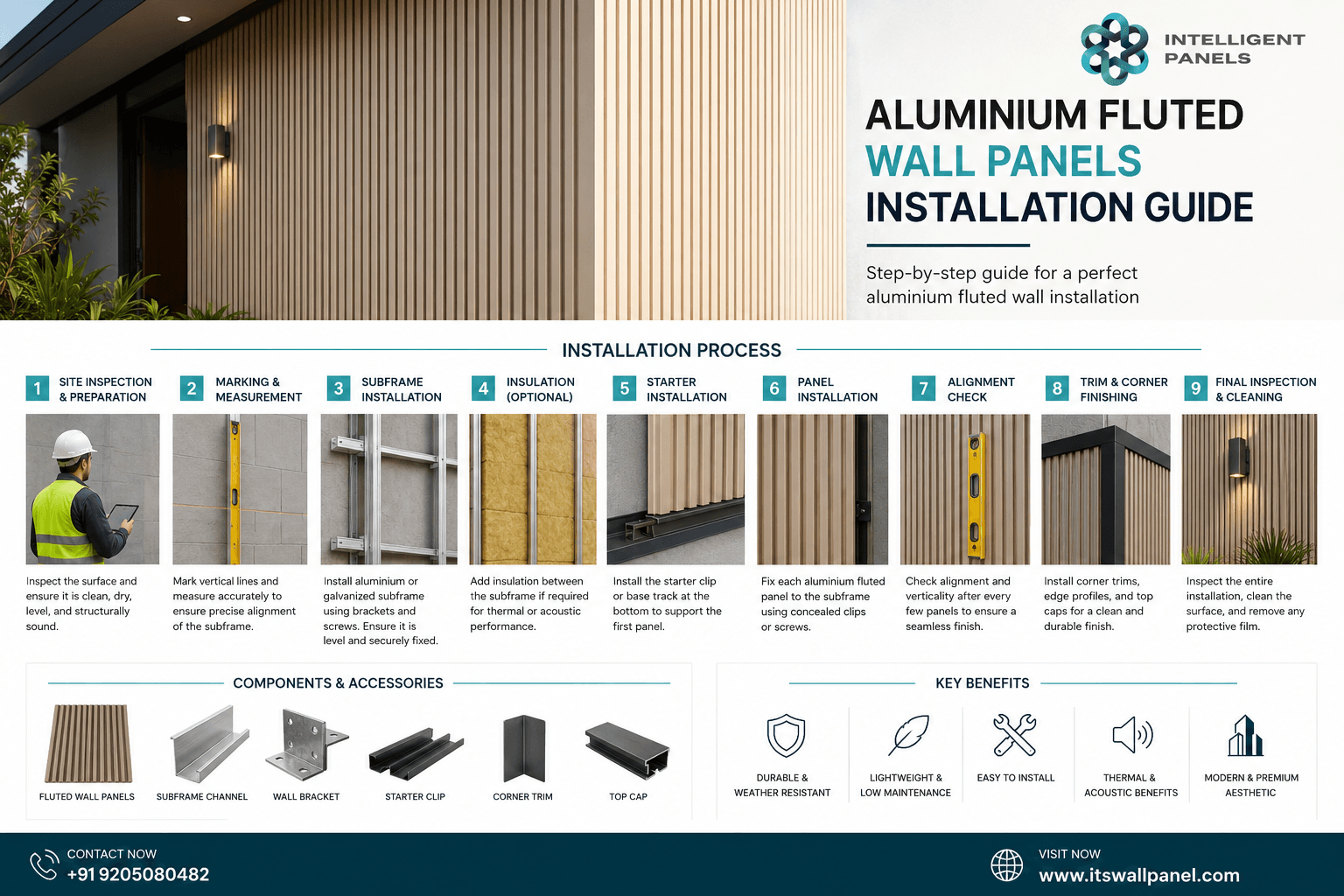
ALUMINIUM CLADDING INSTALLATION GUIDE
Official structural planning, preparation rules, and step-by-step layout assembly parameters for Intelligent Aluminium Cladding (IAC) systems.
Before You Start
Prior to installing any Intelligent aluminium cladding system, it is recommended that you check with local building codes for any special requirements or restrictions. The diagrams and instructions outlined in this guide are for illustration purposes only and are not meant or implied to replace a licensed professional. Any construction or use of Intelligent aluminium cladding (Hereinafter referred to as IAC) product must be in accordance with all local zoning and/or building codes. The consumer assumes all risks and liability associated with the construction and use of this product
 Safety First
When dealing with any type of construction project, it is necessary to wear appropriate safety equipment to avoid any risk of injuries. When handling, cutting, and installing, the following safety equipment is recommended but not limited to: gloves, a respiratory protection mask, long sleeves, pants, and safety glasses.
Required Tools
 Required Tools
Standard carpentry tools are required for a successful assembly: Power saws (desktop or portable), power drills, an electric portable drill, complete structural toolkits, a building level, measuring tape, and a plumb bob.
Site Environment & Work Planning
A clean, smooth, flat, and strong surface is needed to install IAC products correctly. Please check with local building codes before ever installing any type of wall cladding. If the installation does not occur immediately, IAC products need to be put on a flat surface at all times. Never ever should it be put on a surface that is NOT flat.
Plan a layout before starting the installation to ensure the best possible looking wall cladding for your project. Building codes and zoning ordinances generally apply to permanent structures, meaning anything that is anchored to the ground or attached to the house. So nearly every kind of wall cladding requires permits and inspections from a local building department. We recommend drawing out a site plan of your proposed project that you intend to do to minimize errors and make your perfect wall cladding.
 Construction Limits & Limitations
IAC products are NOT intended for use as columns, support posts, beams, joist stringers, or other primary load-bearing members. IAC products must be installed on a code-compliant substructure. While IAC products are great for retrofits, they CANNOT be installed on existing cladding boards
Rear Ventilation Mandates
IAC products CANNOT be directly installed onto a flat surface. It must be installed onto a substructure, so there is adequate and unobstructed air flow under the cladding to prevent excessive water absorption. A minimum of 25 mm (1 inch) of continuous net free area under the cladding surface is required for adequate ventilation on all wall cladding, so air can circulate between adjacent members to promote drainage and drying
Step-by-Step Installation Instructions
Method: Overlapping slates structural installation sequence.
Step 1 & 2: Substructure Joist Layout
Before installation, make sure the wall surface is smooth and solid. It is highly recommended to use joists engineered out of aluminum.
Fix the aluminum joists securely to the base wall structure using anchors. The spacing between joists on-center should be no more than 900 mm. The running spacing between anchoring points along a joist should be 500 mm. Aluminium expansion tubes must be utilized to fix the joist and screw anchoring grid securely
Note: Plan the joist layout with respect to the board length. Double joists are required at the butt seam joints between two separate cladding boards so that each individual board rests safely on its own joist support channel.
Substructure Framing Clearance Clearances:
- A minimum gap of 40 mm needs to be left between the lowest joist edge and the finished floor line
- A minimum structural clearance of 10 mm must be left between the upper structural ceiling and the top edge of the joist.
Step 3 & 4: Cladding Board Mounting
Position the first piece of architectural wall cladding over the structural framework joist, then fix it firmly to the joist using fastening screws. The assembly screws must always be installed cleanly inside the integrated screw groove channel of the cladding panel.
Connect the second interlocking piece of cladding into the groove profile of the first panel. Fix the cladding panel run to the structural joist channel with screws inside its designated screw groove channel.
Continue your wall profile installation by repeating this sequence up the wall surface.
 CRITICAL PRE-DRILL & EXPANSION RULES:
• Always pre-drill a clean pilot hole before driving screws to avoid fracturing or damaging the IAC product profiles.
• Make sure that there is a minimum gap of at least 10 mm between the bottom edge of the starter cladding profile and the ground line to maintain active ventilation paths and offer adequate physical room for environmental thermal expansion and contraction.
• Butt Seams: The butt seam joint gap between two running IAC cladding boards must be at least 5 mm wide to allow for adequate ventilation space and continuous thermal expansion room.
 Fastener Recommendation: We highly recommend utilizing high-grade stainless steel screws for fastening all panels. Screw lengths must be carefully selected and adapted to correspond to the depth and wall thickness of your selected framework joist. Note that fastening screws are not included in standard factory deliveries.
Step 5 & 6: Corner & Trim Profiling
When working on internal corner wall finishes, cut the terminal IAC cladding board cleanly down to a suitable calculated width profile and fix it securely to the joist channel with color-matched assembly screws.
Install the continuing IAC cladding board sections onto the adjacent intersecting wall run. You can utilize a specialized Panel Corner molding trim on outside structural corner exposures as needed. Fix the designated Panel Corner component onto the joist track using your hardware screws, position the second interlocking IAC cladding board firmly over the edge of the first board section, anchor it directly to the underlying joist track with screws, and continue onward.
Panel Corners Universal “L” Trim: These units are explicitly engineered to finish vertical corners. Color-head stainless steel screws should be leveraged when fastening hardware through visible exterior faces of the IAC cladding boards. These color-matched screws remain virtually invisible when installed straight into the profile wave base blending effortlessly into the finished facing colors.
Edging Out Terminations: If you are assembling a terminal cladding course that terminates directly on a mother groove profile and requires a clean perimeter edge, you can seamlessly combine a Panel Connector piece together with a Panel Trim component to lock the assembly.
Windows & Doors Framing Integration
1. Main Panel Cuts: With respect to the physical open spacing around windows or entryway doors that are designated to be covered, pre-cut your cladding board lengths and widths to a point where they sit perfectly flush with the raw building openings after final assembly.
Note: Make sure there is a strict clearance gap of at least 8 mm left open between the window frame casing and the edge of any IAC cladding board profiles located directly above or below the window unit.
2. Window Sills: With respect to structural spaces flanking window bases, cut your selected window sill accent boards down to an accurate running length and width so they rest perfectly flush against the primary IAC cladding panels once fully set.
3. Waterproof Sealant Application: Apply high-grade structural assembly sealant/glue smoothly across either the reverse surfaces of your trimmed window panel boards or directly onto the planned installation surface zone.
4. Miter Cut Finishes: For handling vertical corners flanking either side of an integrated window frame or exterior door portal, an L Corner profile should be introduced. Ensure that all adjoining window trim corners are accurately miter cut at a clean 45° angle to achieve an optimal premium architectural look and finish.
INTELlIGENT ALUMINIUM EXTRUSION SYSTEM
For full architectural design files, catalog specs, and custom profiles